Targeted Modification comprises commands that allow the user to select different portions of the unit cell according to the type, position, size, connectivity or content, or any combination of these properties. The pores and throats that have been selected can then be edited using different modifications.
This facility can also be used to calculate relative permeabilities, by generating effective sizes of voids available to the mobile fluid phase in the presence of a static fluid phase. It can also be used for simulating the change in gas permeability caused by static liquid - an important application being the occurrence of water flooding within hydrogen / oxygen fuel cells.
The Targeted Modification user interface shows different prompts according to whether it is in Run mode or Batch mode - both will be described below.
Target Selection - Run mode
The pores and throats can be selected using a range of different properties, as explained below. The values can be selected by the relevant slider control, or using the text boxes. The two types of control are linked. Invalid entries will cause the font in the text box to go red, and an additional Error notification to appear to the left of the Reset targets button. If uncorrected, an error message will be generated when the Apply button is clicked.
Type: The features can be selected by the feature type, namely pores and/or throats. These selections are useful if you wish, for example, to resize all of the throats in the unit cell to investigate how this changes the permeability.
Position: The void features can also be selected by using the positions of the throats and pores by changing the values in the boxes to select the appropriate void features. The position tools can be used to select half a cell to create a structure that has separated macro and micro porosity.
Size: The void features can be selected by the size of the feature of within a range of feature sizes. In the screenshot below, all voids above 0.0046 μm (4.6nm) have been selected.

The selection control screen during selection of features from a large unit cell
Connectivity: The void features can be selected by how many connections they have. Throats normally have two connections. If you only want to select pores with, for example, two connections change the type to pores only. This can be used to highlight single-connection ink bottle pores within your structure which have implications in the cement industry (see also the website entry regarding ink bottles).
Content: The void features can be selected by the content of the feature. For example you can perform a targeted modification after a fluid uptake or fluid migration simulation and look for features that are 100 % filled. This selection technique can be used, for example, to simulate weathering of a sample by expanding the features that are 100 % water filled by the appropriate size ratio for frost-induced expansion of water. The content section can also be used to select the concentration of solute after a fluid migration simulation.
You can make as many selections as you like, and change them as much as you like, while the yellow Selecting... indicator is showing, as pictured above.
Once you have finalised your selection, wait for the yellow Selecting... indicator to change to green Selected text. Once the indicator changes to Selected, the number of targets selected will also be shown, as exemplified below.
![]() Selections for larger unit cells (typically on a matrix ≥ 25x25x25) will take tens of seconds, so you will need to wait some time for the selection to be made. Note that on some slower computers when using larger unit cells, the number of targets may reset after a few seconds to the total number of voids (e.g. it will revert to 42996 of 42996 Targets selected in the example below). If that happens, re-select the required targets.
Selections for larger unit cells (typically on a matrix ≥ 25x25x25) will take tens of seconds, so you will need to wait some time for the selection to be made. Note that on some slower computers when using larger unit cells, the number of targets may reset after a few seconds to the total number of voids (e.g. it will revert to 42996 of 42996 Targets selected in the example below). If that happens, re-select the required targets.

The selection control screen once a selection has been completed
For this and all selection types, once the Apply button is clicked, the display should change to show the Modification dropdown menu, as exemplified below.

The Modification dropdown menu for a smaller unit cell
Target Selection - Batch mode
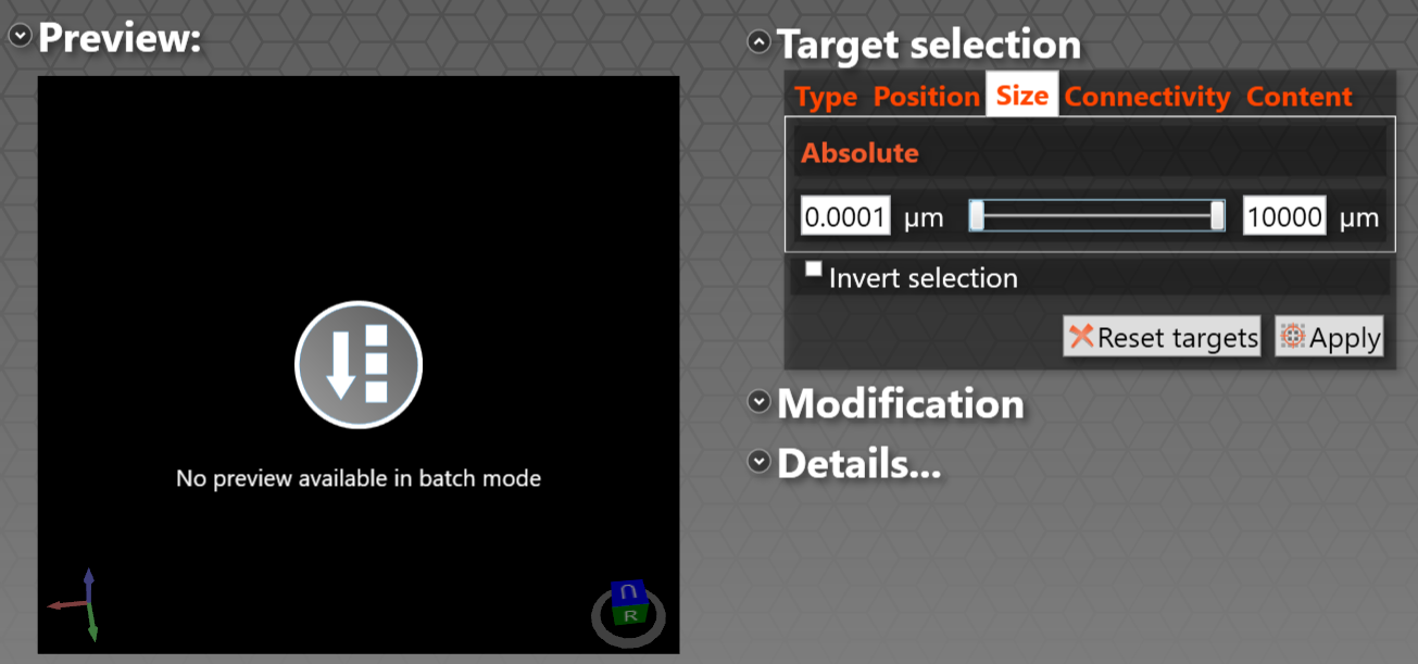
In batch mode, the user interface does not know what the range of pore properties, such as size, will be when it gets to the batch command in what may be a long list of other commands. Therefore in Batch mode, the Targeted selection sets up an encompassing default range for the various properties, e.g. 0.0001 - 10000 μm as shown in the example below.
If you do then select a size range, or other property range, you will yourself need to check that the range is valid, as error messages are switched off in Batch mode.
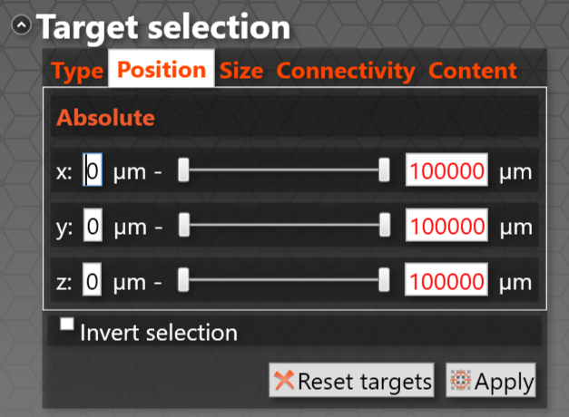
In the case of Position selection, the upper default position is marked on red as a reminder that it is a default position, as shown below. If valid positions are entered, the text will go black.
You do not need to correct the default target ranges when operating in Batch mode - they act as all-encompassing values, so by default everything is selected.
Modifications
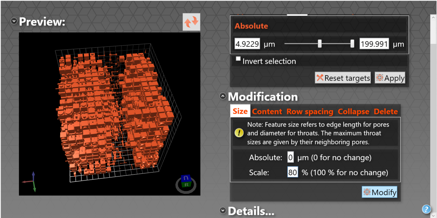
Size: The size of the feature can be changed by an absolute amount using the absolute box, with a negative number reducing the size of all of the selected features to that extent. The size can also be changed by a specific percentage: a percentage value less than 100 will shrink the feature and a value greater than 100 will increase the size of the feature. For example, in the screenshot below, all voids above 4.9229 μm in size are about to be reduced to 80% of their initial size.
However, three rules must be obeyed to maintain the geometric rules of the unit cell: (i) no pore can be bigger than the pore row spacing, (ii) no throat can be bigger than any pore to which it adjoins, and (iii) no pore or throat can have size of less than zero. So, pore by pore and then throat by throat, once the modification you request has been made, if the size of that void that breaks these rules it is modified to be within the permitted bounds.
Content: Any feature selected in the first part of the targeted modification operation can be filled with a fluid available in the materials database. This fluid can be used to simulate the formation damage encountered when recovering oil. The content can be changed to create a concentration gradient for the fluid migration algorithm.
Row Spacing: The row spacing parameter allows the user to change the default row spacing for the x, y and z axis by increasing or decreasing the pore row spacing. This parameter increases or decreases the overall dimensions of the unit cell in all three axis. The minimum pore row spacing is identical to the maximum pore size. Therefore to decrease the pore row spacing below the initial minimum the largest feature size will need to be reduced.
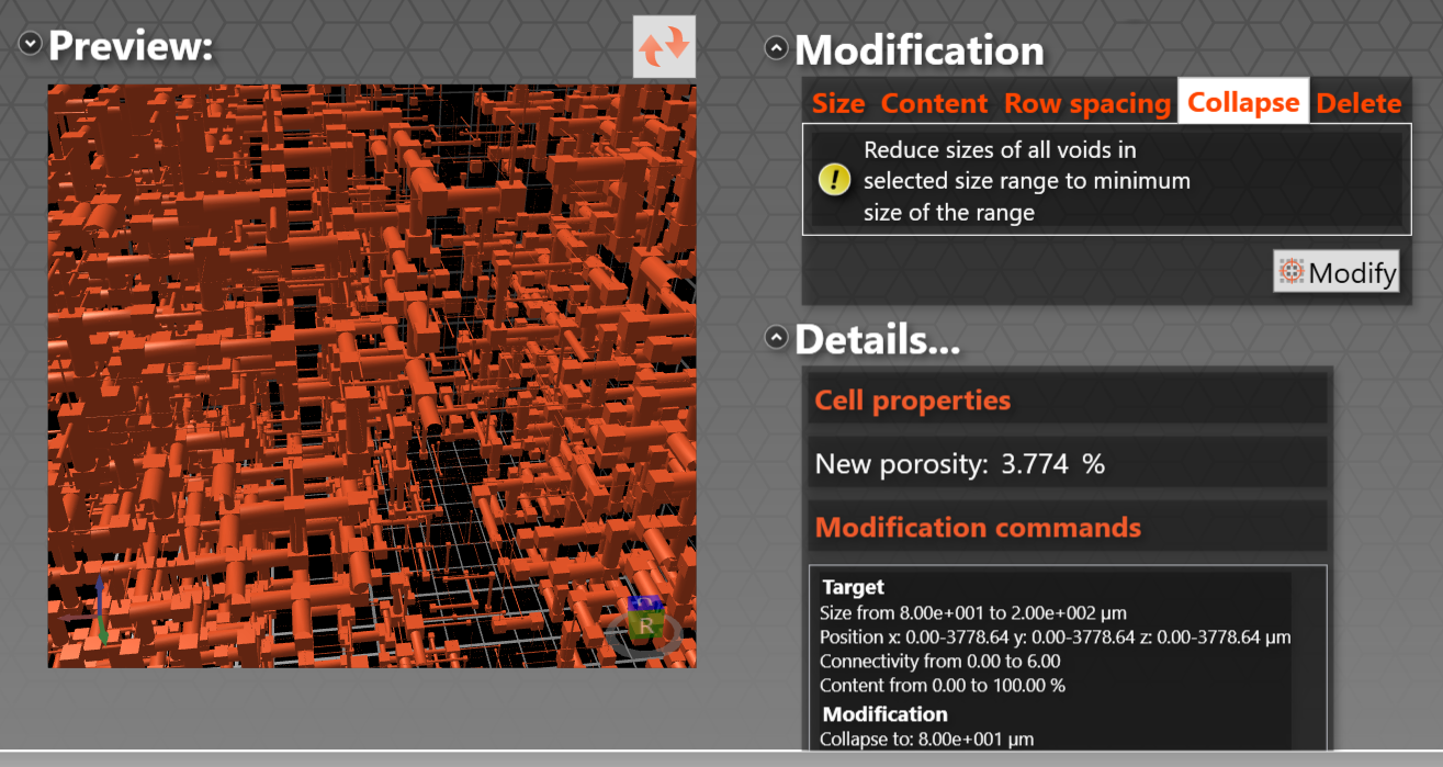
Collapse: This operation reduces the size of all the voids in the selected range to the minimum size of the range. For example, collapsing the selection shown in the screenshot above results in the following screen, in which the structure on the left has been zoomed in to show that voids smaller than 80 μm are unaffected. Also shown is the Details ... dropdown screen which summarises the targets and the modification.
 Note that there is an identified issue with running the Collapse option in batch mode - see the appropriate website page.
Delete: The delete parameter will delete any features selected by the user. This allows the user to change the shape of the unit cell, by removing individual features, or the user could remove a complete layer of the unit cell, converting a cubic unit cell to a cuboidal unit cell. When deleting an entire layer of features ensure only the pores are selected to maintain connections for subsequent calculations.
An example of a targeted modification session, trying out the effect of modifying the properties of a stainless steel sinter, is shown in the PDF targeted modification report.